3D Printed Hinges for a Toilet Seat
The problem
A huge tragedy had struck: one of the hinges on our beloved toilet seat had broken.
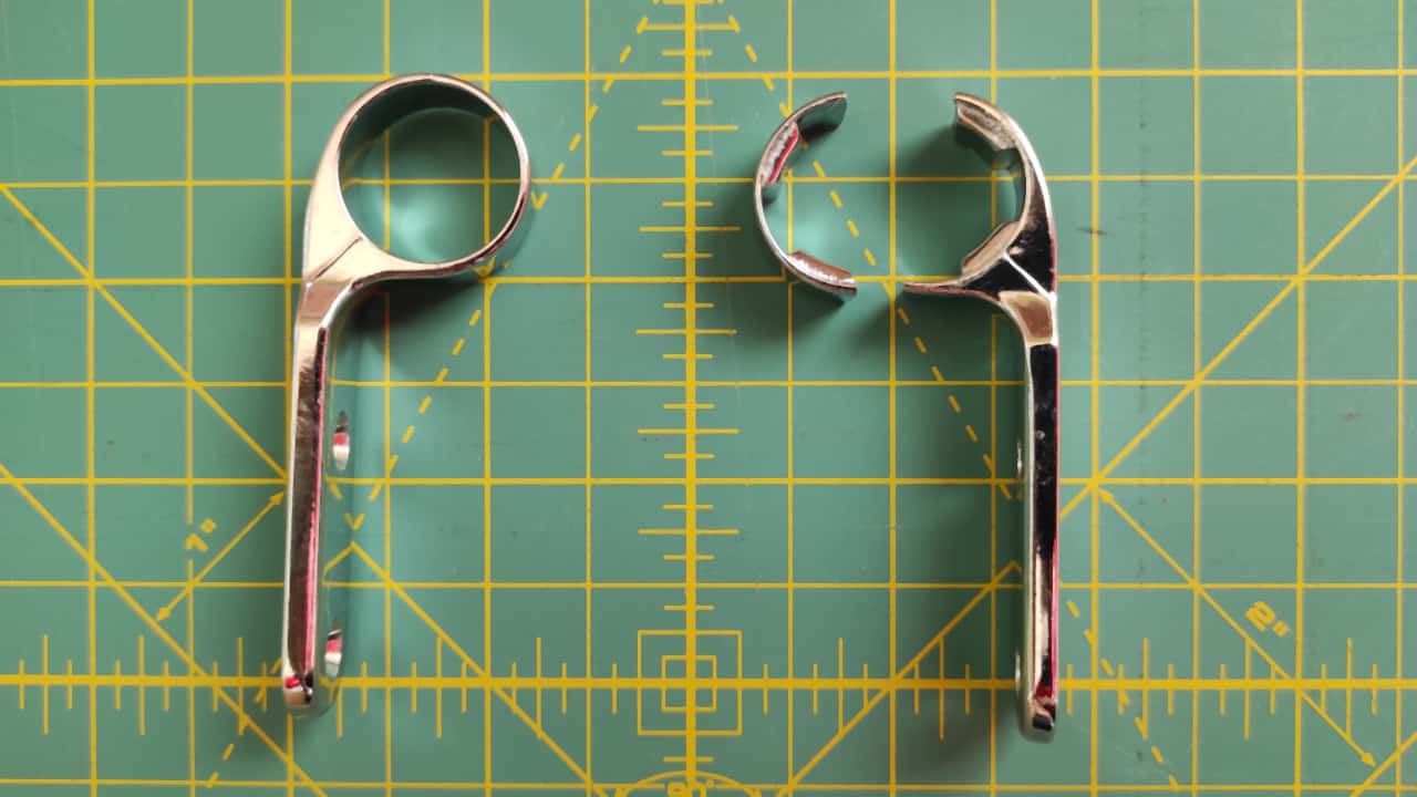
Right where the fitting, which already looked like a rather weak casting, was at its thinnest, barely 1 mm thick.
I am not accusing anyone of planned obsolescence. All I am saying is that if I had to design a part that breaks after a few years, I might also choose a material thickness something like this.
Since I did not feel like going to the shop just for this, I figured I would fix it the hacky way.
Prep and measuring
I grabbed my digital caliper and started taking measurements. It was not especially comfortable to hold the broken pieces together with one hand while measuring with the other, because they kept sliding apart. So I thought I would temporarily glue them together with superglue.
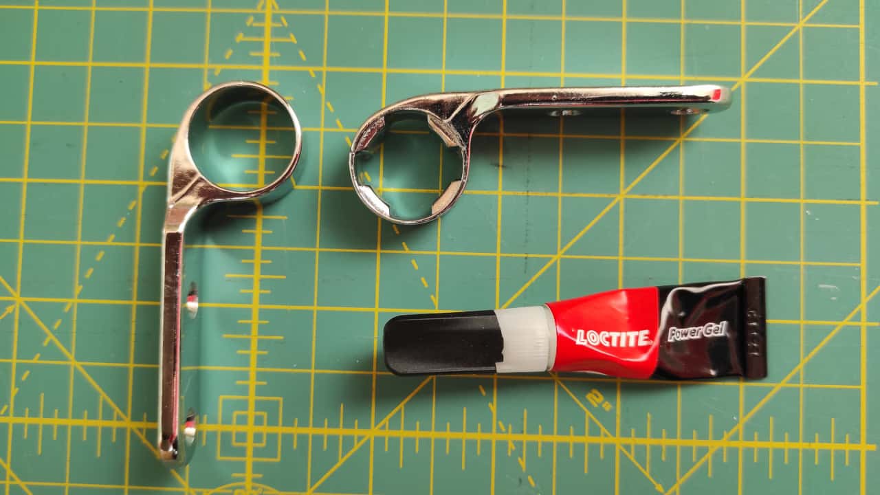
Since the superglue held it together surprisingly well, I thought, fine, this will do. I reassembled the seat, and it has been working ever since. End of article.
3D modeling in FreeCAD
Unfortunately, it was not quite that simple. So I went back to the original plan and started modeling the hinge, so I could make its 3D printed successor.
The piece stabilized with glue was much easier to measure.
Parameters
One of the huge advantages of FreeCAD is that it also supports parametric modeling. In Fusion 360 you can create variables for important values, while in FreeCAD the easiest way is to add them to the built-in spreadsheet and give them aliases, creating reusable values.
I really like this feature for several reasons.
First, you do not have to juggle with random numbers in your head. You can give them meaning and purpose with a name.
Second, it is practical. If the model needs fine-tuning, you only have to change a value in one place, and everywhere that value appears, either by itself or as part of a formula, it updates immediately.
Third, it is usually good for productivity too. I try to add as many values as possible upfront. This forces me to think through in advance what I actually want to make and how. As a result, the modeling itself becomes a linear, almost boring process. There is no need to jump back and forth and possibly redo things several times.
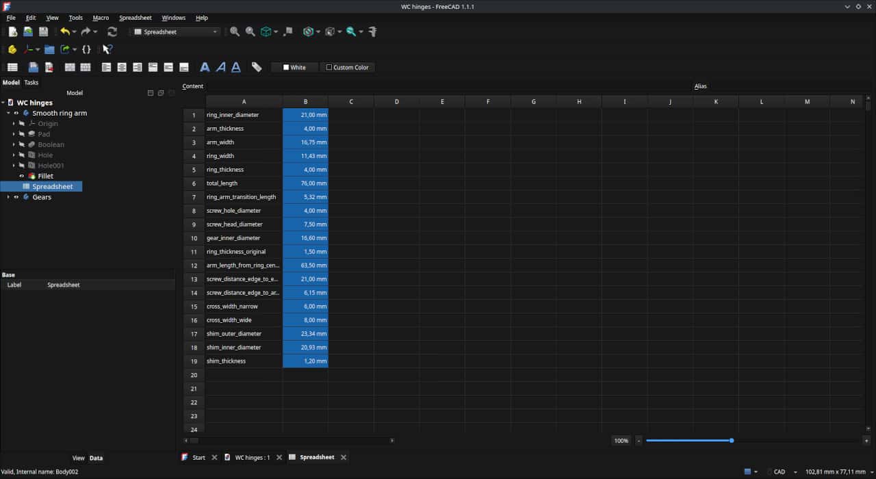
So I added every potentially important width, length and thickness.
Base hinge ring
Although the lugged part (Is it the correct English term? Lugs? Gears? Teeth?) was the one that broke, I wanted to replicate both pieces. Partly for aesthetic reasons, and partly because its counterpart had a similar thickness, so it probably would have broken sooner or later as well.
This plain ring-shaped piece looked the same apart from the lugs, and had the same dimensions. Since this was the simpler shape, I started with this one.
First I created its side-view sketch in the Sketcher workbench. Every value comes from the spreadsheet I filled in earlier.
As you can see, I changed one thing compared to the original dimensions. Instead of 1 mm, the ring thickness became 4 mm. Maybe it will hold up better.
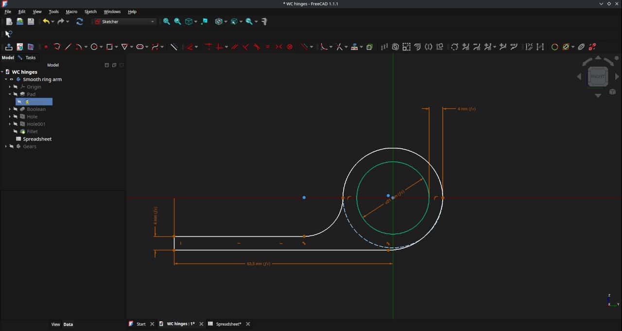
Then I padded this sketch, meaning I extruded it into 3D. I chose a symmetric Pad, because this makes it easier later to find the centerline, for example for the screw holes.
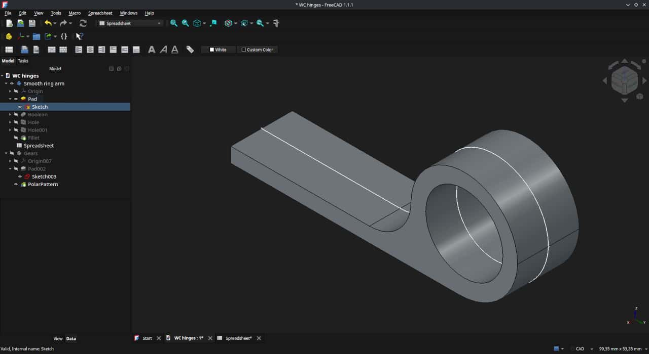
The final shape is not this simple. You can probably see it somewhat in the original photos: the flat part is wider, and the ring part narrows through a transition.
I started with the side-view sketch because the object has more character from that side. That is the more defining shape.
To make it look more like the original, and also to make sure it actually fits in its place, this narrowing had to be solved.
Unfortunately, I did not take a screenshot of this step, and it is somewhat hard to reverse in FreeCAD, so I will just describe what happened.
For the Pad of the side-view sketch, I used the larger value, meaning the width of the flat part.
Then, on the plane of the extruded flat part, I created a new sketch: the top-view silhouette of the hinge. I padded this sketch too. Its size does not need to be exact. The important thing is that it must extend beyond the hinge. Then I used a Boolean operation to take the union of the two objects. This is what it looked like afterwards:
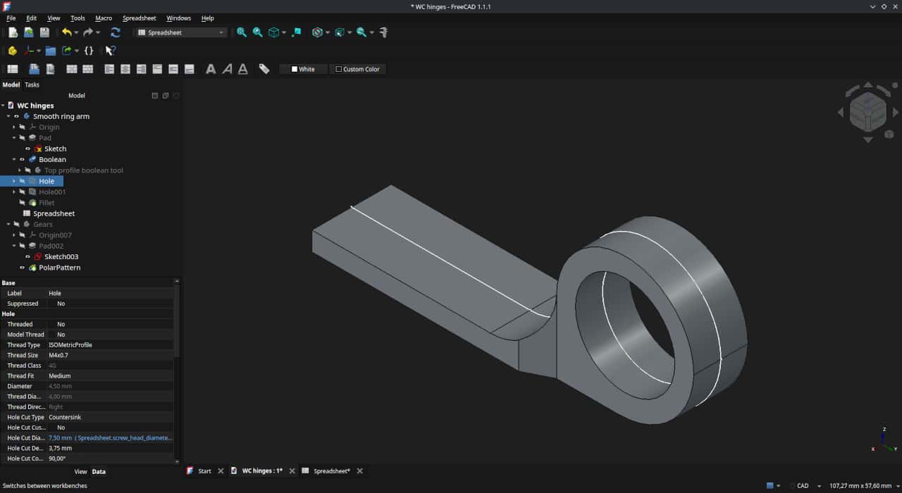
With that, the shape of the part was done. Next, I "drilled" the screw holes.
Once again, I created a new sketch on the flat part. This was basically just two circles. The diameter of the circles is irrelevant, only the position of their centers matters. Then I turned these two circles into holes with the Hole feature. In the parameters, I set the dimensions for the original countersunk chipboard screws.
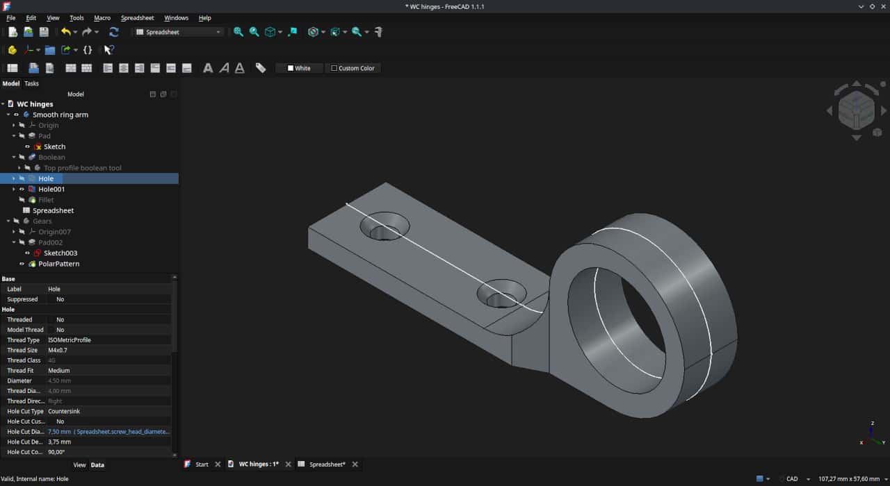
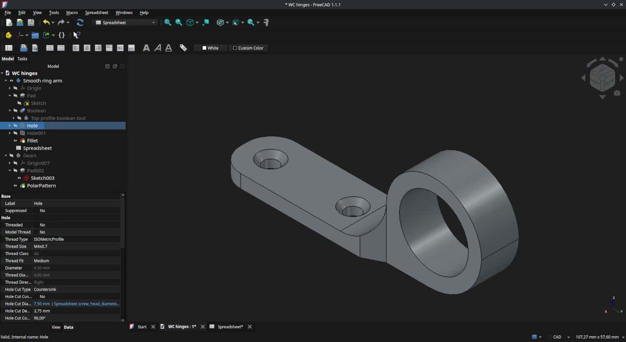
At this point, everything was finally in place. As the last step, I rounded the corners with the Fillet feature. In FreeCAD too, it is worth postponing fillets and chamfers for as long as possible. This saves a lot of headaches if you later need to modify the parameters of any earlier operation.
Lugged hinge ring
As I mentioned, the lugged piece is the same as this plain ring-shaped one, except... it has a few little lugs. Since I am lazy, and this model was only meant for one-time use anyway, I did not overengineer it.
The plan was to create only the lugs, then for printing I would simply export the smooth ring piece by itself once, and then export it again with the lugs added.
Since I started the original side-view sketch with the center of the ring exactly on the origin, it was very easy to create a new object starting from the exact same place.
With a few construction lines and the values from the spreadsheet, the sketch was ready.
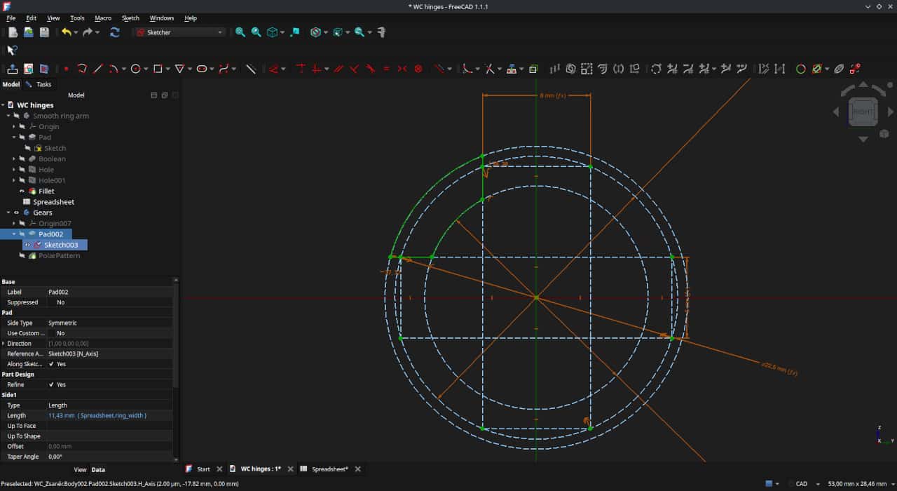
This was also padded into 3D.
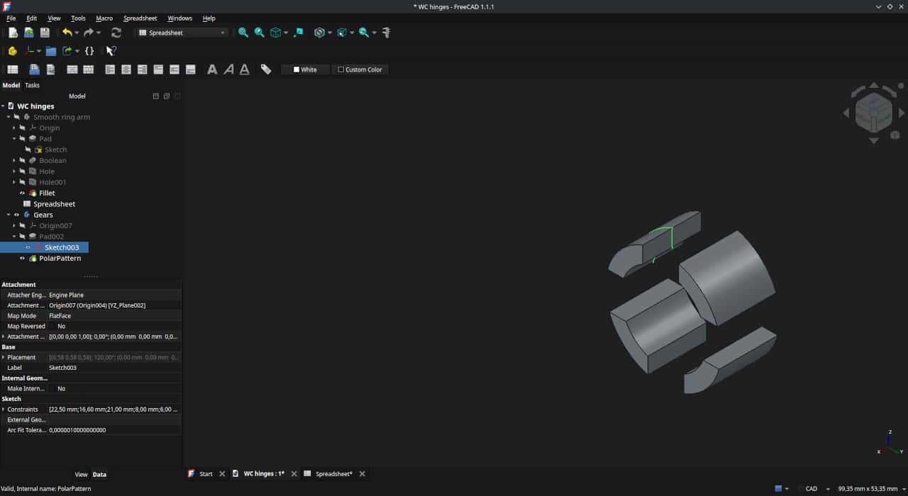
Here is how the two objects look together.
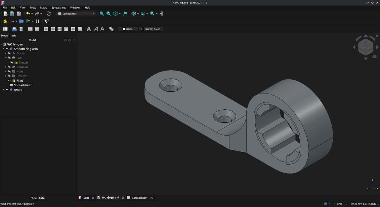
Printing
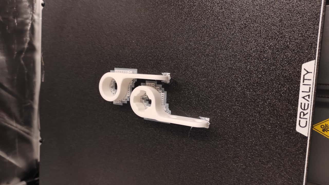
I exported the two variants to 3MF, sliced them with Orca, and sent them to the printer. I printed them lying flat, because this should make them strongest against the force they will experience while the seat is flipped up and down.
The shoulders needed a bit of support.
A Creality Ender-3 V3 Plus spat them out. It finished these two small parts pretty quickly.
Sanding and painting
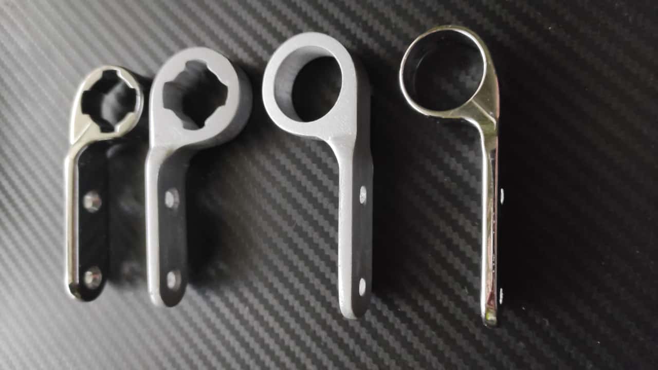
To stop the white plastic from standing out so much where the original part used to be, I sanded it a little and sprayed it with acrylic paint and clear coat.
Unfortunately, I did not have a really good chrome-effect spray at home, so this "silver" had to do.
The result
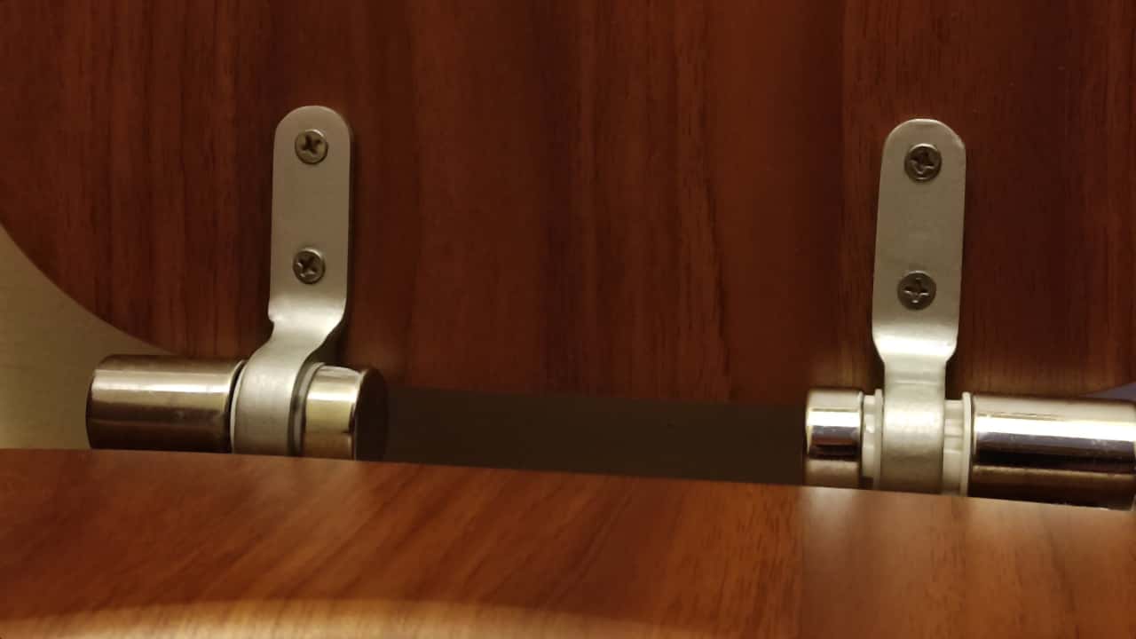
There was nothing left to do but wait for it to dry and reassemble the seat. I think the original chrome and the slightly more satin, aluminum-like finish do not look too bad next to each other. And since I usually sit with my back to it anyway, I do not really care that much.
I could say I do not give a shit, but luckily now I can!
Closing words
Obviously, a toilet seat is not very expensive. On top of that, replacement hardware is available separately for this model, and that is even cheaper. But that is not really what this hobby is about. It simply feels good to exercise the brain with some design work, and the stepper motors by shaping filament that has been gathering dust on the shelf into something useful.
Besides, this gives our significant other one more example of why that several hundred euro investment was absolutely unnecessary.
The construction has been holding up for several weeks now, and I am sure it will last a good while longer. So the operation was a success.